Dynamic On-Site Testing Of Large Structures
In structural dynamics testing, artificial excitation is an important tool in obtaining controlled data on various structural vibration modes. The testing of very large structures such as bridges, buildings, and ships presents an excitation problem in that it may be impossible to shake the entire structure. Relative excitation techniques, where on member or structure is excited with respect to another, also will not work, since no back-up structure is available to push against.
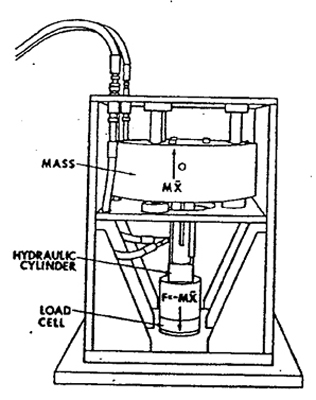
Figure 1: Outline drawing of inertial mass exciter showing major components and operating principle.
The only feasible alternative for exciting large structures is inertial excitation. This method generates a reaction excitation force within a structure by controlled acceleration of a mass. This technique allows a structure to be dynamically excited without back-up fixturing. Figure 1 shows one configuration for generating this reaction force. The mass is accelerated by a servo controlled hydraulic cylinder to generate the output force.
Inertial excitation has been used in testing laboratories by constructing make-shift systems of actuators and masses or by using available systems of counter-rotating weights. The make-shift systems are useful for one specific test, but do not offer the flexibility for general field or laboratory testing. The counter-rotating weight system also has limited flexibility because it is impossible to control the output force over varying frequencies (the output force is actually a function of the rotational speed or frequency.)
Two inertial exciters have been developed to meet the need for a general purpose testing tool. Both use a combination of accelerating mass and a servo controlled hydraulic actuator to generate the inertial force. Both are portable and are designed to be used conveniently on many types of structures.
Applications
The only real limitation to inertial excitation is that the mass of the test structure be much larger than that of the exciter heads. (Loading can seriously effect data taken on structures where the exciter head mass is significant.) Some general applications are outlined below:
- Building Excitation
The units can be used to perform noise and vibration studies on building structures. Artificial excitation can be used to simulate inputs from various types of mechanical equipment (i.e. pumps and motors, compressors, large machine tools). Data taken can dictate equipment isolation requirements and structural changes to reduce vibration levels outside the equipment areas. - Seismic Analysis
the low frequency capability of the exciter heads can be used to simulate seismic (earthquake) inputs to structures such as bridges. The heads require a minimum of fixturing and make field testing relatively easy to accomplish. In the past it has been virtually impossible to field test such structures. - Ship Hull Excitation
Large plate structures, such as ship hulls, can be studied under field conditions. The plate bending modes can be found and maximum stress points determined under dynamic conditions. - Foundation Testing
Large mounting structures, such as those used for steam turbines and generators, can have dynamics that adversely affect operation of the units (i.e. cause bearing or turbine blade failure). This can occur if the mounting structure has a resonance near the operating speed of the units. On-site studies of these structures, using inertial excitation, can pinpoint problems before costly failures occur.
A Typical Seismic Analysis Application
One specific application outlining exactly how inertial excitation can be used is the seismic analysis of an electrical transmission tower. In an earthquake environment, the most critical inputs to a tower structure are in the horizontal direction. If the tower structure is designed with a resonant frequency within the frequency spectrum of the earthquake environment, large motions can occur at the line connection insulators. These large motions can cause mounting failures and downed power lines.
In order to determine if a tower design is susceptible to this type of failure a transfer function analysis between the tower base and the connection points is performed. A small inertial excitation system simulates an earthquake input at the tower base. This system proves ideal because of its portability and the ease of fixturing to the tower.
The required input characteristics are determined from typical earthquake data. * An earthquake of magnitude 6.0 or higher on the Richter scale can produce horizontal ground accelerations of up to 0.6 g in a frequency range of 0.5 to 40 Hz. This is within the capability of the inertial excitation system.
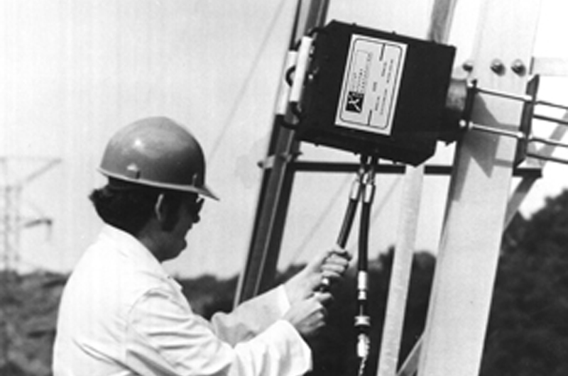
Figure 2: Field test of electrical transmission tower with inertial mass exciter and transfer function analysis equipment.
An actual test was set up to plot the ratio of input force at the base to output displacement at the connection points versus frequency using a transfer function analyzer. All equipment was carried directly to the test site. Figure 2 and 3 show the on-site arrangement.

Figure 3: Inertial mass exciter mounted to transmission.
The test showed that there was no significant amplification between the base and the mounting points for this particular tower design. The use of the portable inertial excitation system made this test relatively easy to perform.
Other methods of getting the same information, such as model testing or computer simulation, would have been much more costly and would have yielded much less reliable information.
Mechanical Design of Units
The units use the basic principle outlined in Figure 1. For most dynamic test applications (i.e. transfer functions, modal studies) sinusoidal excitation is used. For this common case, the output force is given by F=mX, F=output force as a function of time, M=moving mass on the hydraulic cylinder, and Xp=peak hydraulic actuator displacement. The output force is a function of both the moving mass and the available actuator displacement. The actuator displacement is, in turn, a function of frequency (primarily due to hydraulic flow considerations).
In designing two general purpose units, trade-offs between actuator stroke, mass size, and hydraulic power were primarily based on force capabilities, desired frequency response, and portability.
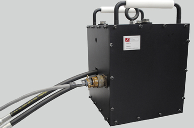
Figure 4: Model ES-301-2 inertial mass exciter which provides up to 1,000 lbs of peak dynamic force.
One unit was designed with a 55 lb mass and a one inch actuator stroke. The hydraulic power supply chosen was a 2.5 GPM, 3000 psi pressure compensated system. This system has 1,000 lb peak dynamic force capacity and has an operating frequency range from 2.0 to 1000 Hz. The exciter head weighs approximately 130 lbs, and is easily handled by two people. (Figure 4).
The second unit has a 250 lb mass, a two inch stroke hydraulic actuator and is used with a 5 GPM; 3000 psi pressure compensated hydraulic power supply (Figure 5). It is capable of 2000 lbs. of peak dynamic force and has an operating frequency range of 0.5 to 500 Hz. This exciter head weighs approximately 600 lbs. A system of lifting eyes is provided with the head so it can easily be maneuvered into position for testing.
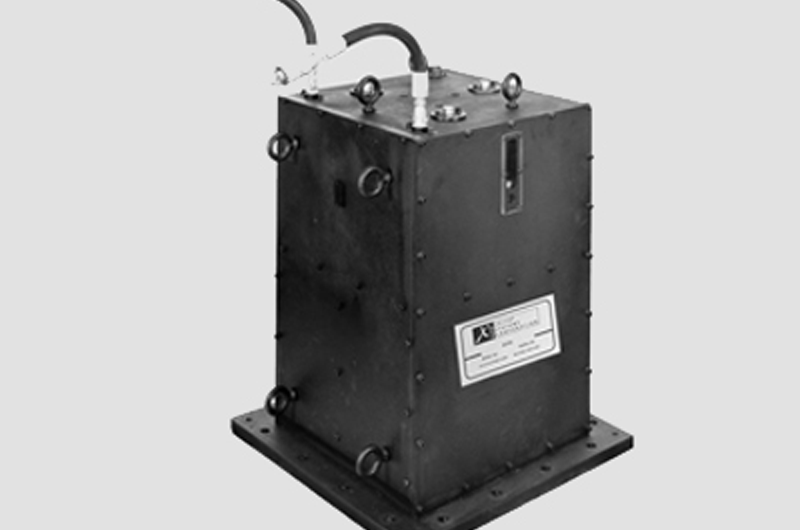
Figure 5: Model ES-302-01 inertial mass exciter which provides up to 1,000 lbs of peak dynamic force.
Electronic Design of Units
To provide the controlled force output over the specified frequency range, a feedback control loop is necessary. Figure 6 shows a basic block diagram of the system.
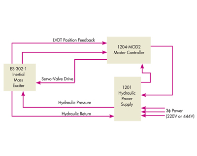
Figure 6: Block diagram of complete inertial mass system showing Exciter Head, Servo-controller and Hydraulic Power Supply.
In order to obtain the maximum possible performance from the heads, the mass must be maintained in the center position of the actuator. This allows the maximum possible motion over all frequencies. The center position is maintained by a low-frequency LVDT position control loop. The dynamic output force is also controlled by a loop around the servo-controlled actuator. A strain gage force transducer measures the output force at its point of application. The controller will maintain a desired output force, within the operating force range, across the entire frequency range.
The combination of exciter head, controller, and hydraulic power supply form a system that provides the most performance (i.e., force and frequency response) for the package size limitations. All system controls are test-engineer oriented. They allow direct movement into testing and data taking by limiting the controls to those essential for set-up and operation.
Summary
Inertial excitation offers a means to dynamically test large structures that are impossible to test using other techniques. Two specialized inertial excitation systems have been developed with force and frequency response ranges tailored to the testing of these large structures. Both systems are portable and offer the ability to do field testing on many classes of structures. Systems such as these should bring the inertial excitation technique to the point of being a general laboratory and field testing tool.
