Jet Engine Multi-Axis Excitation
 Input forces or reaction forces in complex machinery may have independent dynamic components in many different directions. For example, an automobile suspension experiences independent horizontal and vertical forces under normal operating conditions. Also, in rotating machinery, such as turbines, oscillations caused by unbalance may induce multi-axis forces in shrouds and casings. To simulate these forces for dynamic analysis, it is necessary to provide an excitation system capable of inputting and controlling vibration in two axes. A typical application using an Xcite 1100 Exciter System will give an insight into this problem.
Problem
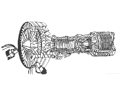
A number of turbine bucket failures within a jet engine operating under normal conditions had prompted an investigation of vibration induced interference between the turbine buckets and the surrounding shroud Figure 1. Under normal conditions, a small amount of interference between the rotating blades and the shroud is evident. If however, the shroud was caused to vibrate by external or induced forces, excessive interference and ultimate turbine bucket failure would occur.
Test Configuration
It was determined that the shroud vibration was in an orbital mode about the axis of the turbine and it would be necessary to simulate this condition to study the problem. The simulation was accomplished by using two Model 1106 exciter heads under displacement control, exciting through the turbine center to 90° at each other Figure 2. The orbital pattern was obtained by setting the output phase relationship between the two heads at 90°.


Test Design Considerations
- MechanicalSince the heads were working at 90° to one another, the possibility for applying high side loads to the heads was evident. The heads themselves will withstand up to 250 lbs. side load. However, to assure long service life, it is desirable to keep side loads to a minimum. For this reason, the heads were mounted on spring structure, allowing lateral deflection and minimizing applied side load.
- Servo-ControlIn order to maintain an orbital patter, it was necessary to maintain the output phase shift between the two heads at 90°. Closed loop phase control is possible over a swept frequency range, but this test involved only discrete frequencies so an open loop phase control proved adequate. The phase at a single frequency was set by shifting the phase of the inputs to the two Xcite Master Controllers until the desired output phase relation (90°) was reached.
Both static and dynamic displacement control were used in this test. Standard LVDT Displacement Kits were used for control of static displacement, along with a 1104-MOD4 Controller, while an accelerometer signal integrated twice through a Real Time Integrator provided the high frequency dynamic displacement signal. The static displacement control was used to maintain a zero-preload condition on the shroud. Physically, this was accomplished by location the head approximately 1/2 the total stroke length from the part and setting the static set-point dial to maintain this position. In this way, tensile and compressive dynamic forces could be applied about the position of zero-preload.
The peak amplitude of the displacement required for this testing was .020 inches at a frequency of 90 Hz., within the capability of a standard 1100 Exciter System.
Summary
Multi-axis testing with standard Xcite Systems is easily accomplished. It is possible to maintain both amplitude and phase relationships between exciter heads over the entire operating range of the systems. A few points must be considered in this testing:
- In setting up a multi-axis test system, serious consideration should be given to avoid high (>250 lb.) side loads on the heads. The use of displacement control is the best way to assure minimum affect of side loads, although force control can be used if special precautions are taken to eliminate side loads.
- Phase adjustment and control between any two heads can be accomplished by shifting the reference signal to the Xcite Master Controllers until the desired output phase relationship is achieved. This may be done open-loop at any discrete off-resonant frequency, or closed-loop, across a range frequencies-not to include a resonant frequency.
Closed loop phase control does present problems when sweeping across a resonant frequency. Structural interaction between two excitation points can cause control stability problems. When moving into a resonant condition, the structure wants to assume a certain mode shape, with certain phase relationships between points on the structure. If the exciters are set at a phase relation different from that of the natural mode, the exciter control system can go unstable. Also, data taken under such conditions will not be valid.